Joining Thick Lines
I need to join thick lines properly. Here is what happens when I don't do that: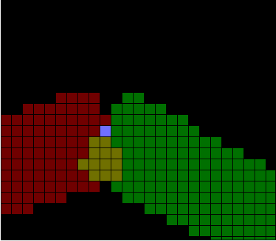
I have two problems:
- Some pixels are painted twice.
- There is a gap between the upper corners.
Identifying the Objective
Before I go into more detail, let's talk about what I want to achieve. Look at the following drawing: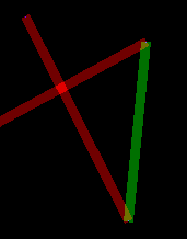
- Don't care about double painting at all.
- Don't have ANY double painting.
- Don't double-paint at line joints, but allow double painting when it is caused by lines crossing each other.
- Double paint line joints, but don't do it for intersections.
Case 3 is more involved. I'd have to distinguish which pixels are being double painted due to line joints. This would require me to test the pixels of the new line against the pixels of the previous line. At worst, I can put stuff in buffers and join them properly, which would take the same time as case 2.
Case 4 doesn't make any sense. I can't think of a real world situation which corresponds to this.
Deciding which option is best depends on the application. If you're going to use the line in an additive display, case 3 would make more sense than case 2. Imagine the above polyline in a single color. The corners would be brighter than the rest of the polyline, which would give it a discontinuous look. It's OK if self intersections are brighter, because that's probably intended.
Case 1 would be useful in a replacing display. If the operations you do with pixels are idempotent, then it doesn't matter if you have some double painted pixels. Figuring them out could be more costly than simply applying the operation twice. Also, if you have case 1, you can easily reach case 2 by simply calling a unify() function.
So, here is what I will do. I will implement case 3. Application of double-paint removal will be optional. When the option isn't taken, the result will be equivalent to case 1. Then I will write a helper function to make case 2.
Possible Solutions
Let's assume that the red line was drawn first, followed by the green line in the first picture. My objective is to figure out the intersection and remove it from the green line. I don't want to deal with this when I'm drawing the red line. It would require me to look ahead and calculate some stuff about the green line while I'm still drawing the red one. I should instead draw the red line normally, and then figure out the redundant pixels while drawing the green line.There are several approaches to this problem:
- Store the red line in a buffer and use it as a lookup table.
- Figure out the intersection using some coordinate algebra.
- Store the border of the red line and make progressive use of it as you draw the green line.
When you have straight edges, as soon as you find an intersection with an edge pixel, you can move forward in the edge for the next possible intersection. Also, when you can't find an intersection, you can be sure that there won't be any more intersections from there on.
This doesn't hold for variable width lines. Intersections may disappear and then appear again as the shape of the line edge changes. Look at the following example.
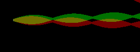
For a while, all goes well and we are able to find intersections and move forward in the red edge for the next intersection. Later on, we don't have an intersection. Now, when we want to paint a green pixel, we have to look at all the remaining pixels of the top red edge to see whether they intersect. This makes it a quadratic time algorithm. I was trying to get rid of a logarithmic factor, but ended up with something worse.
Actually, this algorithm could still be used for variable width lines. While drawing the green line, if we fail to find an intersection with the red edge until we reach the necessary green width, we can continue extending the normal until we reach the next pixel on the red edge (without painting the rest of the normal of course). This would allow us to continue walking on the red edge as usual. However, when the lines eventually diverge to never meet again, we would be spanning the whole area bounded by the lines, looking for an intersection which will never happen. So this is even worse.
Option 2 is also useless for variable-width lines. It would somewhat work for straight edged lines but still it would be imperfect. The reason is that, I use the Bresenham algorithm for drawing lines. Figuring out exactly which pixels are on the border can be very difficult depending on the number format used. A value which can't be expressed exactly in floating point format such as 1/10 can create problems.
Just for fun, I might later implement option 3 for straight edged lines. It would be a fast algorithm with very little lookup. However, option 1 seems to be the best solution for the general case.
First Attempt
When removing extra pixels, I should remove them from the red line instead of the green line. i.e. for each green pixel G, we output all red pixels which are less than G. If we find a red pixel equal to G, we skip over that and then continue with the next green pixel. This way the green pixel list stays intact so that we can use it again when we are drawing yet another one after it.This wasn't hard at all, it just works.
Doing the Corners
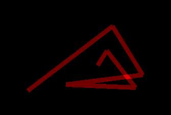
The corners can be joined in three fashions: bevel, round and miter. Miter joints are useful when the angle between the lines is large, more than about 40-50 degrees. They give the impression of solid lines when they meet like that.However, for small angles, mitered joints look really unnatural. The joint itself extends far beyond the width of the lines and that is something we almost never see in the real world. One solution to this is to clip the mitered joint at some point and draw a bevel joint there. This is still not perfect, but acceptable.
Bevel joints look good at almost any angle if the lines being joined are relatively thick. At small thicknesses and small angles, they can alter the perception of the shape quite a bit.
Round joints have a completely different problem. Inside a corner, you have a sharp turn. Outside, there is this nice round transition from one direction to the other. At large angles, this isn't very noticable. As angles become smaller and smaller, this becomes displeasing (to me, at least). Arguably though, this is the best approximation to a real-life pen. You can create sharp angles with a large pen, but only inside the corners.