Filling Polygons
I was doing something else and I had to fill some polygons. My actual case was pretty simple: rotated rectangles. However, I just wanted to implement this properly and be done with it.I thought of several approaches for this. One of them was to divide it into triangles and then paint those. However, this has a lot of issues. Dividing a polygon into triangles has almost the same complexity as filling them directly. It can be done in O(edges) time, but the algorithm for that is way too complex. Also, I'd have to be extra careful about the edges of the triangles to prevent double-painted or empty pixels.
I decided to go with the scanline algorithm.
Basic Explanation of the Algorithm
Here is a good explanation of the algorithm. It still skips some details, which I'll re-discover.We first reorient our edges so that they all
point downwards. After that, they are sorted by increasing Y coordinate of their origin.
The red line below, called the scanline, sweeps the polygon's bounding box from
top to bottom.
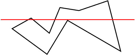
When the scanline encounters a 'top' corner, we add the corresponding edges to our 'active edges' list. When it encounters a 'bottom' corner, we remove the corresponding edges from this list.
At each iteration of the scanline, we look at the intersections of the scanline with the active edges. These intersections are sorted by their X coordinates and are used to output the horizontal line segments to be painted.
The segments are formed in a very simple manner. The first two X coordinates form a pair, then the next two etc. This follows from the following fact: if you follow the scanline from left to right, the first edge you hit puts you inside the polygon. The second one takes you out and so on.
Data Structures
I'm going to scan the polygon from top to bottom. For this, I need to sort the edges according to their smallest y coordinate so that I can activate and deactivate edges with simple checks, without searching anything. During this sort, when two edges have the same origin Y, they will be sorted according to the X coordinate of their origin or target (whichever is different first), in increasing order. The reason for this will be evident later.The edge list will simply be a sorted array. At each y value for the scanline, I will look at the first unused element of the array to decide whether it's to be put in the active list or not. In fact, this will be done before processing the active list so that I can use a more efficient algorithm for the active list when no insertions will be made to it.
The active edge list will be a queue. When processing thru this queue, I will compare the candidate edges' X coordinate to the X coordinate of the current edge and process them in correct order so that the x-sorted property of the queue isn't broken. Since we sorted the edges in the candidate array according to their X coordinate for tie-break, they will appear in correct order during this process.
If edge A occurs before edge B in the queue, it will continue to do so until one of them gets deleted from the queue. This is because our edges do not intersect. In other words, if the X coordinate of A-scanline intersection was less than that of B-scanline intersection at any Y coordinate, it will never grow to be bigger than B-scanline intersection X coordinate. This means that, if we insert edges in correct order from the start, we don't need to sort them later.
Since we're processing all the active edges for one iteration of the scanline, putting them into or popping them from a queue doesn't add any significant run time, it's still linear. Comparing the X coordinates of the candidate and the popped element doesn't add any complexity either. So, we don't need any fancy lookup mechanism. Just a simple queue will be sufficient. This queue should better contain only pointers, since I think that the edge struct will not be so lightweight.
Computing Intersections
In order to compute scanline intersections, several approaches can be used. One of them is to use the line equation. However, this is hairy to implement because of reasons which will be evident later. The best way for this is to use Bresenham's algorithm to compute the edge lines incrementally for each y. This will provide more accuracy as well as some savings on run time cost.However, this isn't trivial. Now that we have restricted ourselves to stepping on Y values, X based edges (where change in X coordinates is greater than that of Y coordinates) are harder to draw. The biggest problem here is the following: for each Y coordinate, we have multiple X values. Consider this drawing:
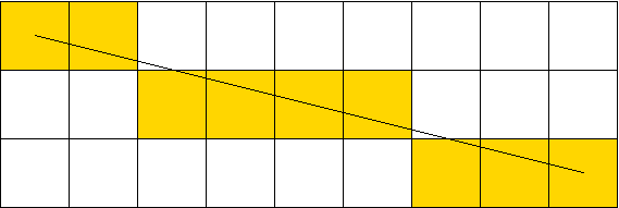
Here I need to maintain two X values for each Y coordinate. Low_X and Hi_X. Hi_X is not necessarily greater than Low_X but is closer to the target of our vector. When the edge in question is a left edge, the smaller of Hi_X and Low_X will be used for the start of the paint interval. When it's a right edge, the other one will be used for the end of the paint interval.
Obviously, for Y-based lines we only have one X value and this problem doesn't occur.
Anyway, instead of maintaining Low_X and Hi_X, I decided to maintain Min_x and Max_x for each edge. This makes much more sense since Low_X isn't used anywhere other than finding these extremities.
The following code is used for drawing X based lines, stepping on Y coordinates. When the advance() function finishes, the X based line will have moved down one pixel.
static void advance_edge_xline(edge_t *E)
{
  int lox;
  E->x= lox= E->x + E->xstep;
  while(E->error<E->threshold && E->x!=E->x1+E->xstep)
  {
    E->error+= E->e_square;
    E->x+= E->xstep;
  }
  E->error+= E->e_diag;
  E->x-= E->xstep;
  E->minx= imin2(E->x,lox);
  E->maxx= imax2(E->x,lox);
}
This is almost the same thing as an X-based line drawing using Bresenham's
algorithm. We simply don't output the pixels, but store the x values to be
used later. Notice how I retract the X coordinate one step back after the
loop. This is compensated for by the addition at the top, which will be
executed in the next iteration.
What's not so obvious is the initialization of such edges. For Y-based lines we have only one pixel for the topmost scanline. However, this is not so for X-based lines as exemplified in the above image. For initializing an edge, we do the same thing as advance().
static void init_edge_xline(edge_t *E)
{
  E->error= 0;
  E->threshold= E->dx-2*E->dy;
  E->e_diag= -2*E->dx;
  E->e_square= 2*E->dy;

  E->x= E->x0;
  while(E->error<E->threshold && E->x!=E->x1+E->xstep)
  {
    E->x+= E->xstep;
    E->error += E->e_square;
  }
  E->x-= E->xstep;
  E->error+= E->e_diag;
  E->xline= 1;

  E->minx= imin2(E->x,E->x0);
  E->maxx= imax2(E->x,E->x0);
}
Another Hairy Bit
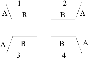
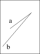
The algorithm worked somewhat OK, albeit with some weird glitch. Whenever an edge ended and another one started, the algorithm would pick these two edges as the boundaries of the span to be output. This resulted in mostly incomplete scanlines. Here is a drawing to illustrate the situation:
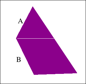
Here, at the corner of A and B, edge A ends and edge B starts. The algorithm incorrectly chooses A and B as a pair to form a horizontal span. This causes the remaining edge on the opposite side to be unpaired and a horizontal gap is formed at the Y coordinate this happens. To overcome this, I detect the situation and remove edge A from the queue without processing it. Its maximum and minimum X values are still used, but it's no longer considered to be an edge on its own right. In this document, I will call this operation "joining A to B".
Another problem was caused by horizontal edges. I took the advice in Link 2 below and ignored them outright. It makes sense when you think about it.
Complexity and Optimizations
The outer loop runs for ΔY iterations, where ΔY is the difference between the maximum and minimum Y values of all edges. In each iteration we go thru a maximum of N edges (the total number of edges). So, the complexity of the main algorithm is O(ΔY*N). N is much smaller than ΔX. Therefore, figuring out the spans doesn't cost much more than doing the actual painting.The main algorithm is prefixed by a sort of the edges, which can be done in O(N*logN) time, if qsort() provided by libc is optimal (it is in musl). This doesn't add a term to the complexity either.
The code I provide below doesn't make use of any multiplication or division. There is one place the mod operator is used: queue access. Currently, the queue is implemented as a (head,len) pair. If I modify it to use a (head,tail) pair, I could replace the mod operator as follows.
If A is guaranteed to be always less than S (A non-negative and S positive), then we can replace [1] by [2], for 32 bit signed integers A and S.
   A = (A+1)%S               [1]

   A=  ((A+1-S)>>31)&(A+1)   [2]
In [2], if (A+1-S) is negative, i.e. A+1 is less than S, then the first part of the expression becomes -1, and the result of the whole expression is A+1. If A+1-S is 0, then the first part becomes 0 which in turn makes the whole expression 0. This provides a wraparound increment for the queue. Modern gcc makes good use of conditional moves, which can make things like the following viable.
A= (A+1)==S ? 0 : (A+1) [3]
Results
Here is a sample rendering:

This code could be used for polygons with holes in them as well. As far as the algorithm is concerned, there is no difference between a hole and a concave-gap. I only need to provide a different interface to specify the holes.
The code can't be used for self intersecting polygons. Many assumptions will fail in that case.
There are a couple of things I don't like about the code. First, arguments are not checked for validity. If you give it only one point, it will loop forever. If you give it two points, it will draw a line. This should be handled.
Related to this, there is no checking for linear triples. For instance, if you have four edges and two of them are linear, then who knows what will happen. This is actually easy to check for, I should do it sometime.
My last grievence is caused by the algorithm itself and isn't so easy to get rid of. This code has to reverse some of the edges you give it. If you specify edge AB when A is at a greater Y coordinate, the algorithm will draw it as if you had specified the edge BA. This will cause problems with regard to the line drawing code I have. As mentioned in my thick lines page, line AB doesn't necessarily consist of the same pixels as line BA. For instance, if you were to draw a thin border around your filled polygon with the same vertices, there could be gaps between the border and the interior.
There are two remedies for this. First, I could modify the line drawing code so that it also draws all lines from top to bottom.
Second method is to draw upward edges in two steps. You first go from the bottom point to the top using Bresenham's algorithm. At the end of that run, you get the correct error value for the top pixel. After this, you can calculate the line from top to bottom using the calculated error as the initial error. This will ensure that you will get the same pixels even when you are drawing the edge in reverse.
I like the first method better. The user shouldn't be bothered with such minute details. A line segment should look the same no matter in which direction you specify it.
I also have some doubt about completely ignoring horizontal edges. Maybe I should just paint them directly before everything else.
In any case here is the demo.
Something Going Wrong Here
I knew that ignoring horizontal edges was dumb. While playing around, I found this gem:
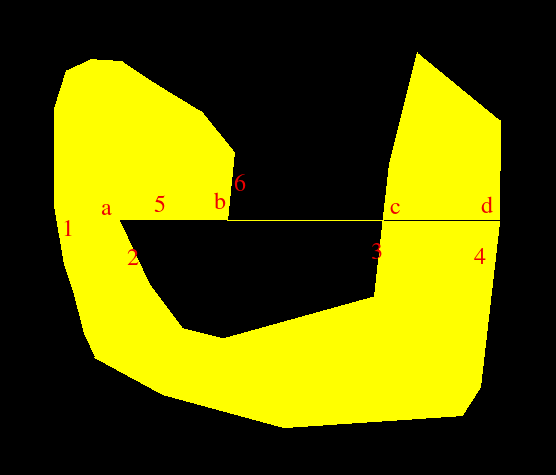
Here, horizontal edge 5 was ignored, with perilous results. Edge 1 was matched to edge 2 and 6 was incorrectly matched to 3, leaving 4 unmatched.
The correct output should be: 1 matches to 2. 5 gets painted by itself. 6 gets terminated (since it joins 5 at that corner). 3 and 4 get matched. In this instance, 2 got sorted before 5, since its x1 is less. If 5 got sorted before 2, things would be much more complicated. I should look into this. It looks like horizontal edges will require quite a bit of special handling.
Trying to Fix the Horizontal Stuff
Here is a simpler polygon with the same problem:
The following coordinates describe the above polygon:
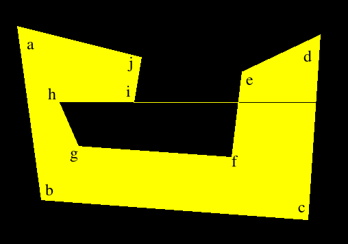
59 109
94 362
483 391
501 121
387 175
372 300
148 284
120 220
229 220
240 154
-1 -1
Simply processing this without ignoring the horizontal edge does work here. This is because hg sorts before hi and is properly matched to ab. Then hi and ji get joined.
Let's see what happens when we reverse the direction of the horizontal line, by going thru the polygon in clockwise order. As expected, the algorithm fails again because the edges ji and ih don't get joined properly. Fixing the edge to read hi makes the algorithm run correctly again. This should have been obvious to me before. We're scanning from top to bottom but also from left to right. So, if a horizontal edge goes thru right to left, we should change its direction.
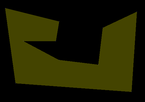
Here is a new example showing the actual shortcomings of the current algorithm.
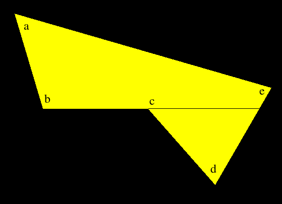
212 146
268 334
476 334
609 485
720 293
-1 -1
When the scanline reaches corner [b], [ab] and [bc] are joined and the horizontal edge is taken as the first edge of the first pair. After this, the edge [cd] starts and is taken as the second edge of the first pair. Hence the line [bc] is drawn. At this point, [bc] is put into the queue for the next round but [ed] is left without an edge to pair with (it's incorrectly assumed to be the first edge of the non-existant second pair). So, nothing gets drawn from [c] to this edge. Finally, [ed] is put into the queue for the next iteration and everything works correctly after that.
In this situation, where a non-horizontal edge ends and a horizontal edge begins, the correct action is to draw the horizontal edge and forget about it. Don't record it as the first element of a pair and don't put it into the queue (obviously).
This is a good fix. It's still not complete because I have work to do regarding the sort order but this will work for the example above and I can do the rest later.
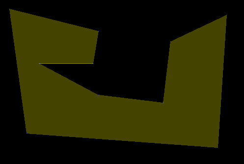
As expected, this fix does work. I was going to put another example which would demonstrate the incorrectness of the sorting criteria. Surprisingly, even though the current criteria are still wrong, the algorithm ends up filling the polygon correctly. Look at this picture, a modified version of the first failure.
59 109
94 362
483 391
501 121
387 175
372 300
240 284
120 220
229 220
240 154
-1 -1
Here, something funny happens. [hi] gets sorted before [hg]. It therefore gets paired with [ab] and is subsequently forgotten about. After this, [hg] gets paired with [ji] and the line [hi] is drawn.
At first glance, this looks correct, but it isn't. When [ab] an [hi] get paired, the span from the left of the polygon to corner [i] is drawn. After that, the span [hi] is drawn due to the second pair of edges. This means that [hi] is drawn twice! This is evident by the following additive display:
So, I do have to correctly sort the edges. Here are the different cases:
Sorting criteria involving a non-horizontal edge A and a horizontal edge B seem to be quite simple. If A and B meet on the left, then A comes first. Otherwise B comes first. The result is here, and looks correct.
The hilighted corners result from the additive display. I have a suspicion though, internal corners might be getting painted twice. I might be wrong due to human vision limitations but it certainly looks like it. In any case, I want to verify this whole thing by writing a flood fill algorithm and then painting polygons using both methods. That will involve some simple-polygon generation, which should be a lot of fun. Anyway, here is the demo as of 25dec16.
A Small Update
I verified the above problem. Some corners are indeed painted twice. It's probably because of X-based edges spanning across multiple pixels on a given row, but fixing that will require me to change the line drawing code to account for adjacent edges. It will be ugly and will take too much time for no good reason. Instead, I will simply filter double-painted pixels at the output stage. All rows are painted from left to right. If I maintain the X coordinate of the last painted pixel on the current row, I can avoid repainting it or anything before it.So, I did that and it works OK. I also verified that the edges conform perfectly to the line drawing algorithm I have, given that you draw the lines top-down. This is the current incarnation of the program. It's still incomplete, below I'll discuss why.
I Got it Wrong
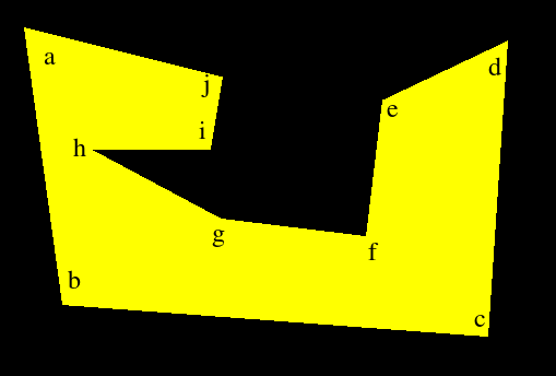
I thought I had handled horizontal edges properly, but I was wrong. Here is an example:
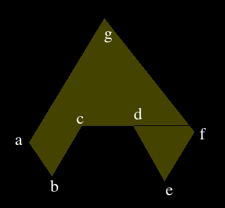
When the scanline reaches the horizontal edge, only [ga] and [gf] are on the queue. [cb], [cd] and [de] are the next three candidates on the array. It's very difficult to handle this situation with the current way I'm handling it, since I have to make decisions based on elements on the candidate array. Instead of doing these things during the main algorithm, I should identify in which class the horizontal line falls into beforehand, while I have the order of the edges intact. We can assume either the pink or the orange part is interior. That makes it 8 cases.
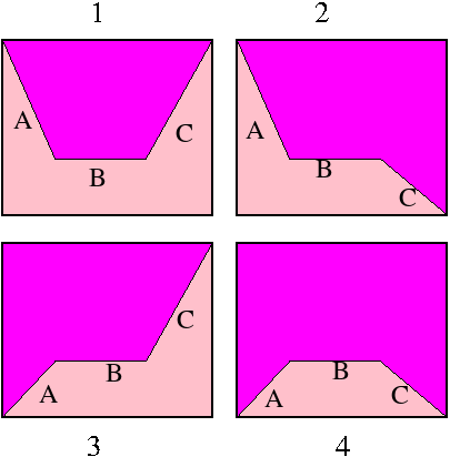
Below, case 1p means the first figure with pink interior. 1o means orange interior.
| Case | Candidate | Queue | Action |
| 1p | B | C | Ignore the edge. |
| 1o | B | C | Draw the edge, but ignore it afterwards. |
| 2p | BC | Ignore the edge. A span from Min_x(A) to the right will be drawn. Put C on the queue and continue. | |
| 2o | BC | Draw the edge to Max_x(C). The span to Max_x(A) has already been drawn. Put C on the queue and continue. | |
| 3p | AB | C | Put A on the queue. Ignore B. A span will be drawn to Max_x(C) later. |
| 3o | AB | C | Ignore B and C. Left edge is A. Record it and a span from Min_x(A) will be drawn later. Put A on the queue. |
| 4p | ABC | Ignore B. Put A and C on the queue without making any of them the right edge. This way a span from the current left edge will be drawn later. | |
| 4o | ABC | Ignore B. A span will be formed between A and C. |
The decision between the 'p' and 'o' cases will be made using the have_left flag in the code. This flag tells us whether we already have a left edge. Here is how I decide about it. have_left column refers to the state of the flag when the 'first candidate' in the above table arrives at the candidate variable. For case 1, if we have a left edge when B arrives as the candidate, then interior is pink. Otherwise, it's orange.
| Case | have_left | Result |
| 1 | 1 | pink |
| 2 | 1 | pink |
| 3 | 1 | pink |
| 4 | 1 | pink |
Results
This worked pretty well. I also fixed a bug in the sorting criteria. I sort by Y coordinates, and then the X coordinate of the origin. Originally, I was breaking ties using the X coordinate of the target. i.e. the code looked like this:compare(A,B) if (A.y0!=B.y0) return A.y0-B.y0 if (A.x0!=B.x0) return A.x0-B.x0 return A.x1-B.x1The third line failed in the following case:
Now, I extend the edge a to a line. Then I calculate the X coordinate of the point on this line where y=B.y1. I compare this value to B.x1.
Here is the latest code. As I had heard before, this algorithm is simple to understand, but difficult to implement correctly. Things to do in the previous results section still apply. Because of the new sorting criteria, the code now has some multiplications and divisions during the sorting process. I could get rid of the division actually, but such tidy-up is for later.
Revisit: It Didn't Work!
I was so confident of my algorithm and it seemed to work flawlessly with the test cases and simple use cases I had. However, there was a hard to fix bug: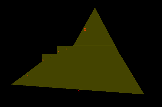
490 100
590 286
690 450
150 410
274 318
274 286
338 286
338 254
402 254
-1 -1
Up until now, I had been concerned with how a horizontal edge would
interact with its neighbouring edges. I didn't take into account the
edges on the opposite side of a polygon. Here, the hilighted edge #1
gets sorted into the incorrect position and thus the algorithm doesn't
find it until after the second horizontal edge has been processed. Something
similar happens with the first horizontal edge. In any case, my
algorithm was flawed and I have come up with a new one.
Now, I don't consider horizontal edges to be edges at all. I simply incorporate them into the neighbouring edges. In this instance, edge 7 would be incorporated into edges 8 and 6. Edge 5 would be incorporated into 4 and 6. After that both horizontal edges are forgotten about.
The incorporation works as follows. Each edge has an 'extension x' coordinate for each of its endpoints. If the start or end point of an edge isn't part of a horizontal edge, this extension is the same as the normal x coordinate of the point. Otherwise, the extension is the other x coordinate of the neighbouring horizontal edge. In this example, edge 6 would have an extension at the start point and the end point, incorporating both horizontal edges 5 and 7. Edge 8 would only have an extension at the end point, extending the last pixel of the edge to the leftmost pixel of edge number 7.
After this extension, there is nothing else to do regarding horizontal edges. I simply fill the polygon using only the non-horizontal edges while using the 'extension' info to properly paint the fill.
Here is the latest code which seems to handle all the failure cases I have found so far. I hope this is the last iteration.